
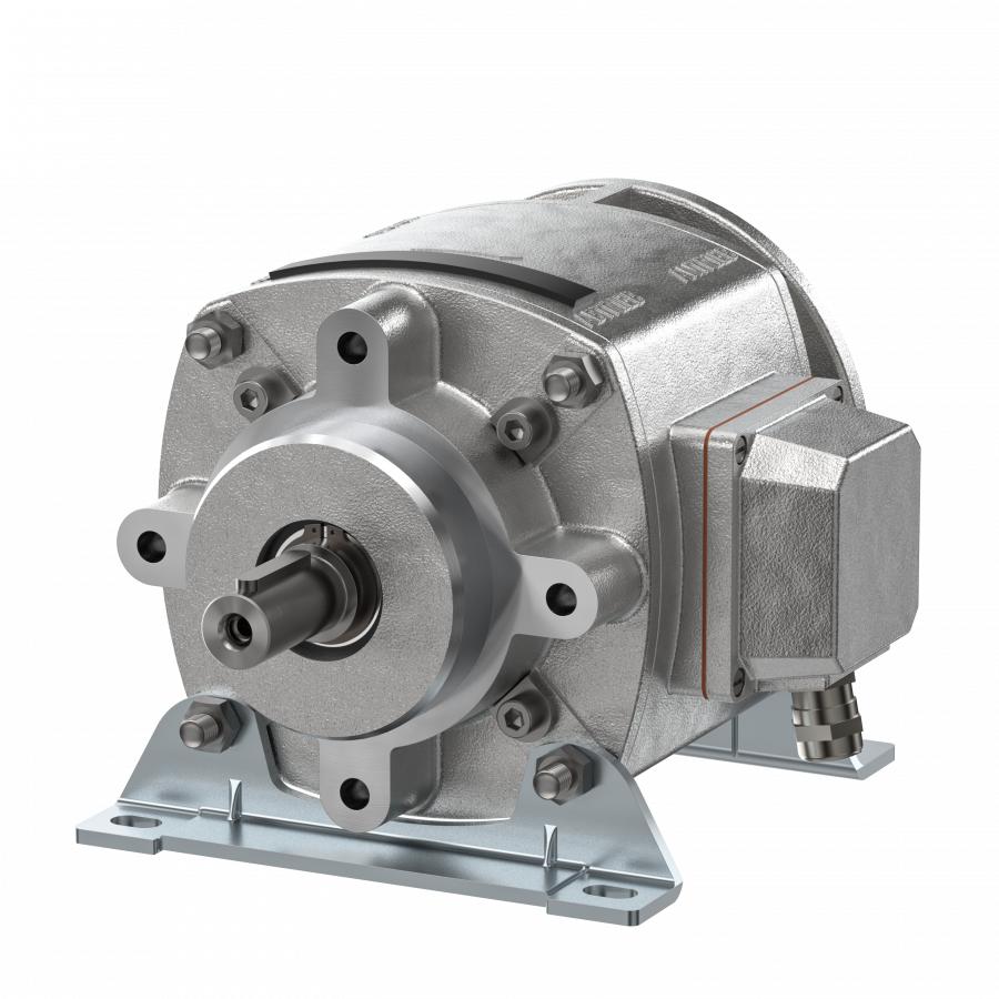


Description
About Electromagnetic clutch-brake combinations
The same air gap adjusting device is provided for each output cover. The sequence of functions is described below.
The description of the patented adjusting device applies to both versions. If required, the air gap can be compensated as follows:
- Loosen the four screws (1) in the housing cover at the output end until the pressure on the compression springs beneath it is relieved but do not remove them completely.
- Remove the cover from the slot in the housing. Insert a cylindrical pin into the bore which then becomes visible. This pin must be capable of radially twisting the ring (2).
- Turn the ring in the direction of the arrow. When you feel resistance, turn it back by one scale marking (equal to the rated air gap).